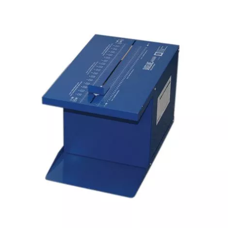
Sit n Reach Flexibility Box Features
- This flexibility tester performs sit n reach flexibility tests
- Sturdy metal construction with a built-in foot plate and a maximum stretch indicator that remains until reset
- Scales include- fitness, program, Cooper Institute/YMCA, AAHPERD
- The Deluxe model offers an adjustable start point
- A Deluxe model can be used to normalize scores to account for variations in the arm and leg length of the person being tested
- Scales printed in inches and centimeters
Why use a Modified Tester?
- A standard flexibility tester does not compensate for variations in the length of the arms and legs of the person being tested.
- People with long arms and short legs have an advantage, while those with long legs and short arms are disadvantaged.
- The Modified Flexibility Tester measures normalized trunk and hamstring flexibility.
- You can still use this as a standard tester by securing a hitch-pin to produce a “standard” start point.
What to buy with Baseline Sit n Reach Flexibility Tester
- Baseline Tactile Semmes-Weinstein Monofilaments
- Baseline Tactile Disposable Monofilament Evaluator
- Baseline Mechanical Pinch Gauge
How to use Baseline Sit n’ Reach Trunk Flexibility Box?
Box Assembly
- Assemble the box using the top (TP), bottom (BP), sides (SP), foot plate (FP), and 8 5/8” slotted screws and wing nuts.
- Begin with the BP on the floor. Line the FP (groove side up) holes with the holes on the front of the BP.
- Line both SPs with the holes on the BP. The SPs should be positioned inside the lips of the FP, TP, and BP.
- Insert each of the bottom screws from the outside and tighten each of the wing nuts on the inside.
- Position the TP on the top, with the Baseline logo facing right. The lips should cover the SPs and FP.
- Insert the screws from the outside and tighten each of the wing nuts on the inside.
- A screwdriver may be needed to anchor the screw while tightening the wing nuts.
- Remove the backing from the self-adhesive chart and adhere it to a side of the box (SP) so that it is easily read.
Slider Assembly
- Insert the channel mount screws through the holes on the finger plate and put one Teflon spacer through each screw.
- Place the screws into the channel on the Top Plate (TP). Insert another spacer into each screw under the Top Plate (TP). followed by a spring and then a wing-nuts.
- Hand-tighten wing-nuts.
Sliding Top Channel
- Place the sliding channel in the Top Plate groove with the scales readable from the footplate.
- Make sure the 4 holes for the stopper are on the side closer to the back of the unit. Thread the channel mount screws into the side holes on the top plate (TP) with the threaded part of the screw pointing into the channel and tighten.
- These screws hold the Sliding Top Channel onto the top plate (TP).
Locking the Sliding Top Channel into place
- Mount the stopper to the Top Plate (TP) on the holes provided.
- This stopper is used with the modified flexibility tester to hold the Sliding Top Channel at one location.
- The nuts on the stopper may have to be adjusted for the stopper to touch the sliding top channel.
Baseline Reach Trunk Flexibility Tester User Manual